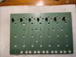
Start by placing the banana jacks on the front panel
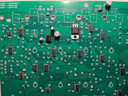
Put in place the LT1054 IC, the LM7805 and the 1N4001 protection diode, solder them and remove any extra leg from the back
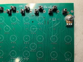
On the back of the board add the mini jacks and the 10k potentiometer (remove the anti rotating tag), solder everything on the back being careful that the jacks adhere perfectly to the board
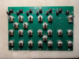
Same goes for all the 100k potentiometers, remove the anti rotating tag and put them in place as in picture.
Proceed to solder them
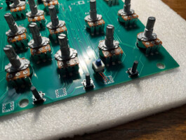
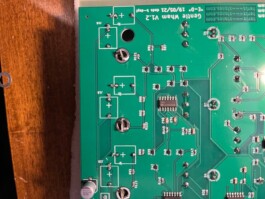
On the lower part of the back of the board put the six tactile switches in place and solder them (any orientation will do), then place the seven DPDT switches in their respective footprint being careful to match the side with the two stripes (see picture).
You may want to solder just one leg, check if they all perfectly adhere to the board and only then solder all the other legs
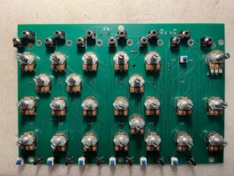
This is what your board should look like at this stage
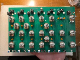
Put all the LEDs in place, but do not solder them yet!
The cathode (short leg) must be inserted in the square pad, the anode (long leg) in the circle shaped pad
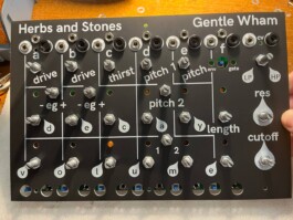
Time to merge the front panel with the PCB.
Be sure that all the potentiometers are in a straight position and double check that all the anti rotating tags have been removed
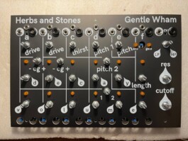
Once everything is in its place, tighten the nuts of the potentiometers and minijacks.
Push all the LEDs through their own hole on the front panel and solder the legs to the PCB
On the back of the board solder the banana jack leads to their respective holes
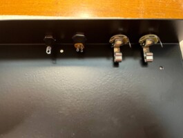
On the metal enclosure put the GND banana jack, the DC connector and the two 1/4"jacks as in the picture
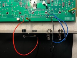
Use some wire (not included) to join the footprints on the board to their respective connector.
Be sure to share the ground between all of them
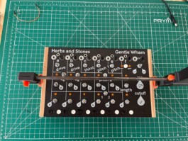
Put the switch caps on their respective switch (see picture).
The tactile switches need a bit of glue to keep the cap in position.
Screw the hex spacers to the front panel and through the PCB, then you can merge the pcb+panel with the metal enclosure and put the remaining m3 screws on the bottom of the enclosure
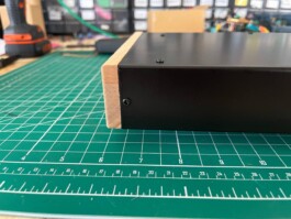
You can now add the wooden side panels and use the wood screws to keep them in place.
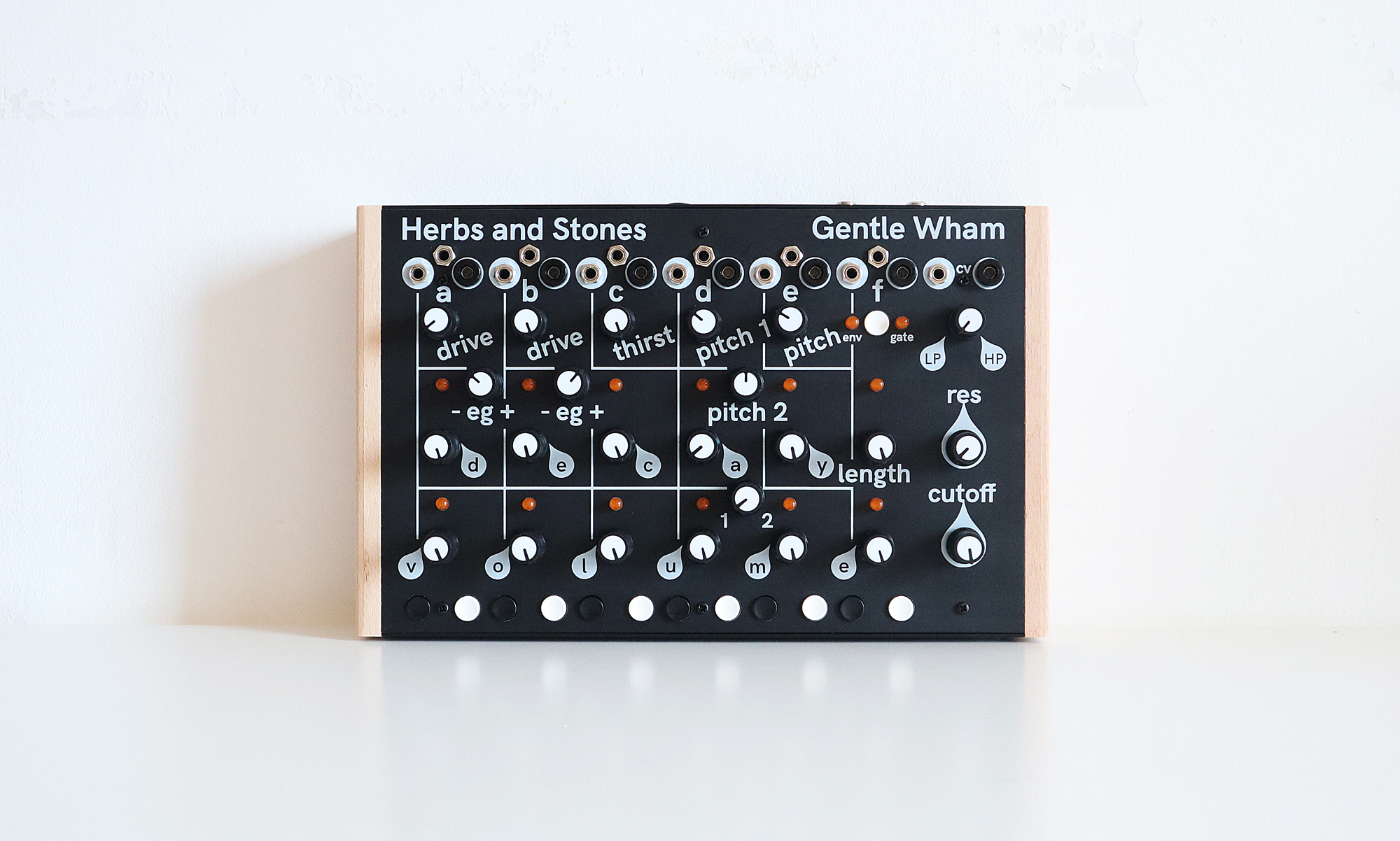
Add the knobs to the potentiometers and you're done!
Now it's time for some not-always-gentle percussive synthesis :-)