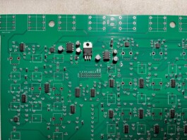
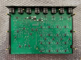
Start by placing and soldering all the components that are on the front of the board:
LT1054 ICs
LM7805 voltage regulator
1N4001 diode
Cut the legs of the diode and solder them across pin 3 and 6 of both the LT1054 ICs on the back of the board
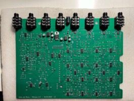
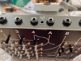
Place the 8 1/4" audio jacks and the DC jack on the front of the board and solder them
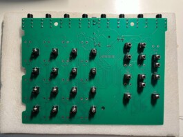
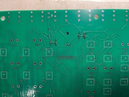
On the back of the board place all the 1/8" jacks and once checked that they all are in position solder them
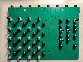
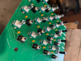
Same goes with the potentiometers: put them in place like in the picture (see the difference between the two types of potentiometers) and solder them to the PCB
Put the LEDs in place (the short leg goes in the square shaped hole) but do not solder them yet!
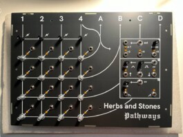
Put the front panel in place, put on all the jack and potentiometers nuts and tighten them. Push the LEDs through their respective holes in the front panel, once everything is in place you can solder them and trim away the extra LED legs.
Now put in place the top part of the enclosure where the audio jacks are
Fix all the brass spacers as in picture
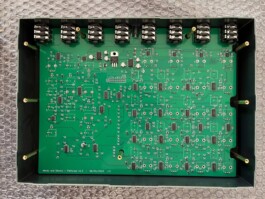
Almost there! Put in place the remaining parts of the enclosure as in picture, once everything is in place put on the back panel and tighten the remaining 9 screws.
Done!